Arduino pro mini 3.3V wireless nRF24L01+ board – Remote control project

Transmitter:

After I made the wireless boards I wanted to find a project to use the boards in.

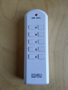
Because a friend had a non functional remote controllable helicopter we wanted to make it work again.

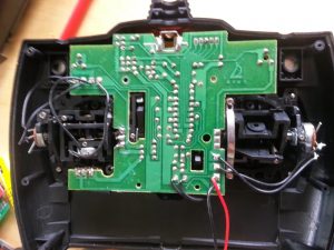
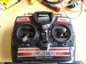
So I figured that fixing the remote controller, by replacing the original PCB with the wireless board was a nice project.

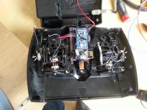
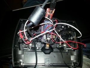
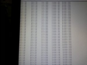
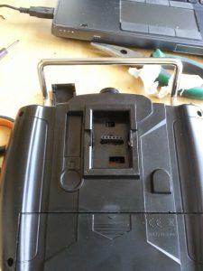
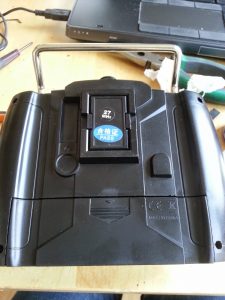
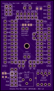
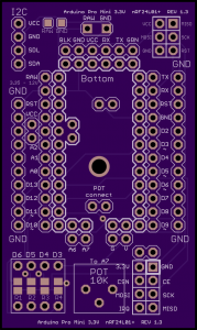
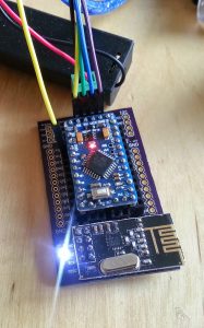
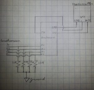
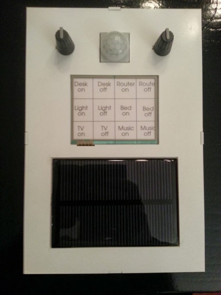
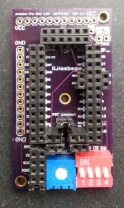
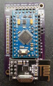
After hooking up the hardware I started coding. The first and easiest thing I coded was the code to read all the potentiometers. The coding of the transmitter was A bit more challenging. Because I wanted to transmit all 5 the potentiometer values in one sequence. I ended up putting the values in a array which was a success. Because I couldn’t test the transmitter code without a receiver code I had to code an other wireless board as a receiver. The transmitted data that the receiver receives can be seen on the serial monitor in figure 4. The finished code can be found on my github. To ensure the controller can be updated and debugged without having to open the controller I created a FTDI port on the outside of the controller (figure 6). The FTDI port can be hidden behind a cover as shown in figure 7.

Receiver:

The receiver code enables the receiving Arduino to receive data from the nRF24L01+ chip and process that data. Because the analog-to-digital converters (ADC) have a resolution of 10 bits  and the ‘normal’ analogWrite function only has a resolution of 8 bits the data values need to be remapped. The remapping of value ranges is easily done with the function map. After these values have been remapped the can be used to control the motors of the helicopter. Because the tail rotor needs to rotate in both direction a h-bridge is required. For this project I used a L298N dual h-bridge board, although we only use 1 h-bridge but this was the cheapest and fastest option to get. Because the board also has an 5 Volt regulator on board, we can use it to power the Arduino in the helicopter from the LiPo-battery. The L298N board is no longer in use because it would fail at random. My friend designed a PWM controller board to power the main rotors. The board uses 2 IRF540 MOSFETs to channel the power from the battery to the motors. These MOSFETS unfortunately need a drain to source voltage of at least 4.5 V which our 3.3v Arduino doesn’t supply. This is solved by using two NPN transistors for each MOSFET to power the MOSFETS with a high enough voltage.

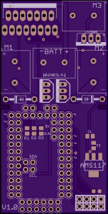
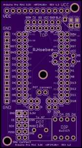
After successfully testing the helicopters lift capability we decided to design a new board (Figure 8) which integrates all the different components in 1. The new board uses different MOSFETS for easier and more powerful motor control. These MOSFETS are easier because the can be directly controlled with 3.3V and thus do not need extra bipolar transistors to boost up the voltage. The new MOSFETS are IPU06N03LA MOSFETS and are made by infineon. A small comparison can be seen in Table 1. Because the new MOSFETS have a lower Rds(on)  they have lower power losses due to lower Drain-source on-state resistance, which also has the benefit that the MOSFETS become less hot.

Table 1: MOSFET comparison.

IRF540N 06N03LA Desired
Vds 100V 25V Min 7V
Rds(on) 44 mΩ 5.7 mΩ Max 10 mΩ
ID continuous 33A 50A Min 20A
ID pulse 110A 350A Min 50A
Id at 3.3V and 25°C 23A+ Min 20A
Id at 5V and 25°C ±27A 100+ Min 20A
Figure 1: Original non-functional PCB
Figure 2: Wireless board placement testing
Figure 3: Remote wired to the Arduino
Figure 4: Transmitted data from the remote
Figure 5: Finished remote
Figure 6: Uncovered FTDI port
Figure 7: Covered FTDI port
Figure 8: OSHPark render of the integrated board

Arduino pro mini 3.3V wireless nRF24L01+ board REV1.3

I’ve created a REV 1.3 version of my nRfL01+ board for the arduino pro mini 3.3V. This board still uses the same ports for connecting the nRF24L01+ module as REV 1.2 and 1.2.2. It also has the potentiometer and dip-switches that REV 1.2 and 1.2.2 have. But now there are separate I2C and a SPI connections. And the Raw input voltage can be measured using analog input A6 (as long as it is below 6.6 volts). The brd file can be found here.

Figure 1: TOP, render by OSH Park
Figure 2: BOTTOM, render by OSH Park
Figure 3: Testing the board

Simple Home Automation

The project

I’m currently working on automating my remote outlets. To start I’m going to build a central remote control unit. The first step is controlling my Impuls outlets (Figure 3) and if that’s successful I’m going to try and add some automated features like shutting all my power outlets off when leaving the room. Controllin my Beamish BY-7E light switch (Figure 2) is also in the planning. I bought the Impuls outlets in the Action, a series of shops in the Netherlands. For 10 euros you get 1 remote and 3 outlets which is a seriously low price. The Beamish BY-7E was bought on dx.com for about 13,50 dollar.

Hardware

Before opening the remote outlets I was planning on adding an nRF24L01 module or a Bluetooth module to each outlet. But after opening the outlets I found the relatively unknown and badly documented … chip in them. But in the transmitter I found the commonly used and good documented HX2262 chip. The HX2262 chip is also compatible with the SC5262 and PT2262 chips and can be replaced by an Arduino running the right software. These chips make my projects a lot easier, cheaper and safer, because the receiving units are already finished when buying them. The only thing I need to build is my own transmitter. This is done by connecting a 443.29 MHz super-regeneration transmitter that uses On-Off Keying (OOK) to an Arduino. The module I used (Figure 4) costs about 2 dollar on dx.com and can be bought on many different sites.

Because I find using normal buttons a bit boring and because you can’t change the button layout easily I decided to add a touchscreen to my control unit. The touchscreen I’m using is a Nintendo ds lite touchscreen, because these are easy to read out and are about 3 dollar per unit. I use the BOB-0917 break outboard from Sparkfun to connect the touchscreen to my Arduino. I’m not really happy with this board because it needs a piece of paper between the touchscreen cable ribbon and the connector to make a good connection. And this board also lacks pull-up resistors for a stable analog read out. But for now I don’t have an other option so I use a breadboard to connect the pull-up resistors. The current test rig can be seen in figures 5 and 6. The next challenge for me was powering the Arduino without using a power cord. I chose a 18650 battery and a solar panel combination because this combination can power the Arduino for a long time. Well that was the theory at least, so I began testing. After testing I concluded that this was a good combination if the Arduino could be in power down mode most of the time. In graph 1 you can see the result of my testing. You can also see that if the Arduino isn’t in power down mode most of the time that the power consumption of the Arduino is to high for these power sources. But extra power saving measures like desoldering the power led have not been done yet, but may be included in the future.

Software

For transmitting the right codes with the Arduino the best library to use is the Remote Switch library (not written by me). And for the touchscreen I have written my own library based on this tutorial. I think that using libraries makes the code better readable. Update: The library and Arduino code now work in perfect harmony together.  Here is the beta version of my touchscreen library and here is the beta Arduino code that goes with it. You also need the RemoteSwitch library which can be found in the link above. I’ve created a github repository for this project here and will be using this to update my code and not the links from above.

Update 10-02-2014:
I created an other library to get the Arduino file smaller and more clearer. This library wasn’t working at first but Boris a friend of mine fixed the library for me. The new code and a movie demonstrating the setup will be uploaded this week, but currently I’m to busy to do that.

Update 14-02-2014:
New code was uploaded to Github and the video is uploaded here.

Hardware enclosure
All the hardware from the main control unit is going to be enclosed in a custom box that I’m going to make. The boxed is going to be made by gluing plates of PMMA that are cut with a laser cutter. Renderings of the box can be seen in Figure 7 and Figure 8. The cutouts in the box are for placing the solar panel, touchscreen, PIR-detector and two potiontiometers. The potentiometer and PIR-detector are for enhancements that are going to be added later on.

Figure 1: Impuls remote
Figure 2: Beamish BY-7E light controller
Figure 3: Impuls remote outlet
Figure 4: 433 MHz transmitter
Figure 5: Hardware setup
Figure 6: Power usage test
Figure 7: Main hardware enclosure non see true
Figure 8: Main hardware enclosure see true
Figure 9: Painted body
Figure 10: The master control box

GY-80: BMP085 + 9-Axis Magnetic Acceleration Gyroscope Module

Hardware

The GY-80 board consists of a BMP085, ADXL345, L3G4200D and a HMC5883L.

Figure 1: GY-80 top
Figure 1: GY-80 top
Figure 2: GY-80 bottom

BMP085

The BMP085 is a digital pressure and temperature sensor. It can  easure from 300 to 1100hPa and  as a pressure resolution of 0.01hPa. It can also measure temperature from 0 to 65°C with a resolution of 0.1°C. With both pressure and temperature readings combined the altitude can be calculated.

ADXL345

The ADXL345 is a 3-axis digital accelerometer. The sensors range is user selectable: ±2G, ±4G, ±8G and ±16G. The sensors bandwidth is also user selectable from 1600Hz to 3.125 Hz.

L3G4200D

The L3G4200D is a three-axis digital gyroscope. It has 3 user selectable scales: 250, 500 and 2000 dps.

HMC5883L

The HMC5883L is a 3-axis digital compass. Its full scale range is ±8 gauss.

Software

Because I want to read all the sensors with 1 Arduino I have chosen to communicate with all the sensors via I²C. After searching I came to the conclusion that I was best off using the Adafruit_sensor, Adafruit_ADXL345, Adafruit_BMP085_Unified and the L3G4200 library. The adafruit libraries can be found on: adafruit github and the L3G4200 can be found on: pololu github. I refer to the github pages of the owners of the libraries because that way you get the most up-to-date libraries and I don’t get in license troubles. I’ve written and combined code to make all the sensors work in one sketch. The code can be found here. The next step is to use the sensors data to control a helicopter.

Arduino pro mini 3.3V wireless nRF24L01+ board REV1.2, updated to include REV 1.2.2

The first batch of Arduino pro mini 3.3V wireless nRF24L01+ REV 1.2 boards has finally arrived.

This is the first board I ever designed and a good learning experience. The board was designed with Eagle 6.5 and manufactured by OSH Park. Making the design in Eagle was a bit more complicated then I at first thought it would be, because I couldn’t find any existing library that fulfilled my criteria. So I ended up creating a library for every different component in the design. Because I find that using autorouter in Eagle is quite useful if you have given it good design rules I created my own design rules for the autorouter. The dru file can be found here.

Hardware

The nRF24L01+ board is connected according to the RF24 library, see table 1. The IRQ pin of the nRF24L01+ can easily be disconnected from the D2 pin of the Arduino, this is especially useful because the D2 pin is one of the interrupt pins of the Arduino. The IRQ pin is connected when using a jumper connector on the IRQ connect pins.

Table 1: nRf24L01+ routing.

Signal: RF module pin: Arduino pin:
GND 1 GND
VCC 2 VCC
CE 3 9
CSN 4 10
SCK 5 13
MOSI 6 11
MISO 7 12
IRQ 8 2

As can be seen in Figure 2 the board has a 10 kΩ potentiometer and 4 dip-switches on it. The potentiometer also uses a connection with a jumper connector but now on the Pot connect pins. This means you can also disconnect the potentiometer from the Arduino freeing up the A7 pin. The 4 dip switches are wired to pins D3, D4, D5 and D6.

Figure 1: Render by OSH Park
Figure 1: Render by OSH Pak
Figure 2: Board without nRF24L01+ module and without Arduino
Figure 2: Board without nRF24L01+ module
and without Arduino
Figure 3: Board with nRF24L01+ moudule and Arduino

Progamming
The pro mini doesn’t have a built in USB connection, that is why you need some extra hardware to program the Arduino. I use Arduino Uno with the ATmega328 removed from the board, you could also buy an FTDI programmer which aren’t expensive. But if you already have an Arduino Uno lying around its free.


Software

The first thing you need to do is make sure you get a library for the nRF24L01 or nRF24L01+. I personally prefer and use the Rf24 and RF24Network library from maniacbug which can be found here. There are also a few examples that can be found in the library.

Update
On REV 1.2 I unfortunately made a mistake, which renders the dip switches useless. This was because I didn’t check how to properly connect the switches. I”m currently at the end stage of a REV 1.3 where the dip switch problem has been resolved and a few other enhancements where made. If REV 1.3 is finished I will upload them to this blog. REV 1.2 can be found here.

REV 1.2.2 upgrades
The REV 1.2.2 is the improved version of REV 1.2. The dip switches are now correctly connected to the Arduino, but require a 10k 0805 SMD resistor per switch. The IRQ connect and nRF24L01+ connections have switched places to ensure that the v, g, A7 and A6 connections are easily accessible when the nRF24L01+ module has been attached. Also a few minor silkscreen changes have been made. The REV 1.2.2 brd file can be found here.

Top view 1.2.2
Figure 4: Top view 1.2.2
Bottom view 1.2.2
Figure 5: Bottom view 1.2.2