The first part of the internship, was to automatically place windows in the windowsills of a train wall.
As second part of my internship I made an app to control the ABB IRB7600 from an Android smartphone.
The first part of the internship, was to automatically place windows in the windowsills of a train wall.
As second part of my internship I made an app to control the ABB IRB7600 from an Android smartphone.
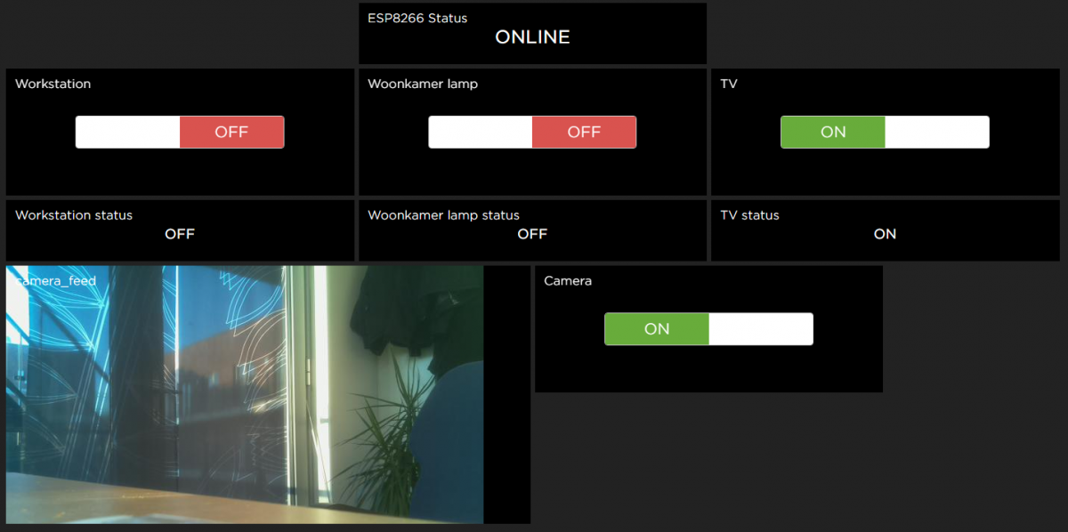
This post is a update of my previous post. I ditched the idea of replacing my remote with a fixed touchscreen remote. Instead I wanted to be able to control everything through the internet. I decided to start with using the Adafruit IO service. The hardware used for this project are a Raspberry Pi 3, Pi camera, remote controlled switches, ESP8266 NodeMCU and a 433MHz transmitter.
The NodeMCU was used to make a wireless connection to the internet. It uses the MQTT protocol to get feed data from my Adafruit IO dashboard. This feed data determines if the transmitter needs to turn off or on a specific switch. Currently the switches are only controlled by the online commands (or manual override with a remote control). But automation scripts can easily be made, which can be handy when going on vacation. As can be seen in Figure 1 there are still a lot of IO pins unused on the MCU so upgrades can be connected.
As can be seen in Figure 2 the online dashboard also contains a live camera feed. This camera feed runs from a Raspberry Pi 3 with a Pi camera. Currently the camera is in a testing location. But when properly placed it will see my complete room. Because there is no QOS support from the online dashboard a different solution had to be created. That’s why the status of the received input feeds is send by the NodeMCU to the dashboard. This way we can make sure that the feed update was received and processed correctly. The ESP8266 is programmed with a last will and testament, so if the connection is lost the broker sees this and publishes the testament which donates that the module is OFFLINE. If the connection is open then the ESP8266 status is set to ONLINE.

The delta robot was a semester long project in my second year. In the first half the delta robot had to be designed, build and programmed using a PLC and HMI. The pill location would be entered manually on the HMI. The second half of the project the control needed to be automated by a vision system. And for extra difficulty the pills would be moving on a conveyor belt. The budget for the project was extremely low so that’s why it is not the fastest delta robot by far. But the knowledge gained from the project is very valuable.
Pills where picked by a vacuum gripper and the delta robot moved by using hobby servos. The vision system comprised of a normal webcam and a program written in Python and using OpenCV to process the images and control the PLC. The robot also had an automated calibration function, which used a cross-laser to calibrate the x and y axis of the robot. And to calibrate the height a vacuum sensor was used in combination with the vacuum gripper.
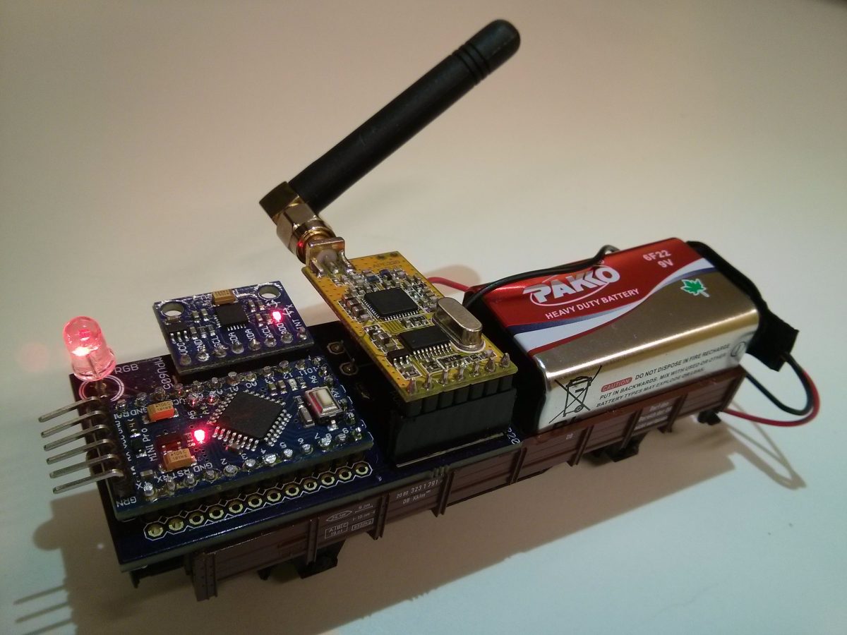
The second project of my Mechatronics education was to build a cart that could sens and record acceleration data and predict the carts path. The acceleration data also needed to be collected for post processing and analysis. My part of the project consisted of programming the Arduino and creating the python Gui and data analysis program. It also consited of designing and building of the hardware.
The setup can be seen in Figure 1. The cart gets accelerated over a predetermined path until it reaches the ramp. After it reaches the ramp the carts needs to give a visual indication if the carts turning point is between point a and b or not. This indication has to be done before the return point of the cart is reached.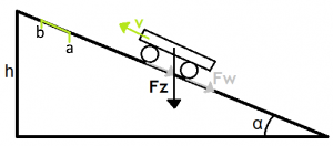
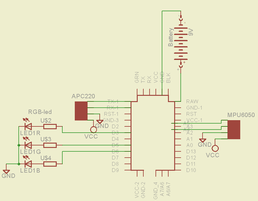
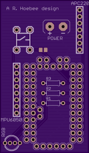
The on-board hardware consists of a battery, a RGB-led, a Arduino Pro mini, a MPU6050 and a APC220. This can be seen in Figure 2. This electric circuit was turned into a PCB as can be seen in Figure 3. The MPU6050 consists of a 3-axis accelerometer and a 3-axis gyroscope, for this project only the accelerometer was used. The APC220 is a transceiver operating on 433Mhz, which is used to send and receive serial data from the Arduino to the PC. Because of the Arduino’s limited processing power and the need for a quick calculation, the Arduino uses two setpoints to determine if the carts return point is between a and b. The setpoints are compared to the measured acceleration of the cart during the acceleration phase. These two setpoint where calculated in advance. This was possible due to the fact that the tracks position was known and the friction coefficients where derived from a test setup. If the cart was not able to reach point a, then the RGB-led would turn orangje. If the cart would pass a but not b the RGB-led would turn green and if the cart would pass point b the RGB-led would turn red.
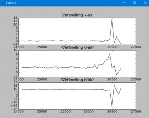
The acceleration data also needed to be recorded for later use. All groups decided to store their data onto an SD-card. Except for our group, we decided to transmit the data to a pc. We did this so that in order to processes the data the cart did not needed to be removed from the setup and analysis of the data could be a lot quicker. The pc used a python script to record the data from the card and store it in a CSV file. This CSV file could also be read by python so that recorded session could be easily analysed. See Figure 4 for recorded session. A other benefit of using python and wireless data acquisition is that it was also possible to give a life plot of the data.
I’m currently doing the IMEP project during my study. This project has three international weeks one in the Netherlands, one in Germany and one in Belgium. During the Germany week we learned to use and program FANUC robot arms. To do this an assignment had to be completed. The assignments had to be done in groups of three. Our assignment was to program the FANUC LR 200iC robot to sort cylinders. These cylinders are notched with 1 to 4 notches. (See figure 1). The robots starts with picking up the cylinders. Then the picked cylinder gets scanned be a laser sensor. The cylinder is then placed in the right location based upon the number of notches.
I have decided to switch from using blogger to using my own site. One of the main reasons was that I wasn’t happy with the layout options in blogger. Most of the time it was a real pain to try and place a picture on the blog. Also uploading a video to blogger meant that the video quality would be downgraded.
All my old posts from blogger have been copied to this new website. I just need some extra time to copy over all the pictures and video’s. Also comments aren’t copied over, but this will stay this way.
The first project of my mechatronics education was to build a automated bridge with only two button and an emergency lowering of the bridge in case of high winds. The buttons where used for giving a up and a down command or if both buttons where pressed for an emergency stop. I used the following components for the bridge:
Although the bridge worked according to plan it was an over-complicated mess .This included the use of an Op-Amp for boosting the voltage of the “wind meter”.
The use of two Arduino’s because one Uno did not have enough memory to run the complete code. And for the communication between the two Arduino’s I used three ‘three state bits’. This was done bu using PWM signals with a Low-Pass filter to stabilize the ‘second state’ enough so the second Arduino would measure this correctly with it’s analog input. The second Arduino would receive a low, middle or high signal on three inputs so was capable of receiving nine different states. These nine different states would correspond to nine different pictures on the display.
Measuring of the bridges angle was done by using a 6 DOF MPU6050 and using the accelerometer data to calculate the angle. The acceleration of the bridge was only partial compensated by averaging five consecutive data samples.
An Optop-coupler circuit was also needed due to the motor interfering with the I2C used by the MPU6050.
I’ve bought multiple mcufriend 2.4 TFT LCD shield, but nearly all of them came with different drivers and display problems. Two of the shields have drivers which I couldn’t identify. It took me hours to find how control the first display correctly. But finding the driver for a second display went a lot faster.
For people who don’t want to spend a lot of time searching for the right library I combined the Adafruit TFTLCD library with peaces of code I found on the internet and with my own code. I don’t know who wrote parts of the code, because of all the time I spend searching and trying different libraries. If you have written any of the code I used please contact me and thank you for making life easier.
Code written by:
If I buy another TFT LCD shield with a different driver I’ll update the library.
As of know the library includes the following drivers:
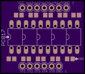
Because of a school projects, which was a battery powered Automated guided vehicle. I found the need for galvanic isolation of a high power and a low power circuit. The high power circuit was connected to a LiPo battery and because of this there was a safety risk. To reduce the safety risk the high power circuit had a circuit breaker and components that could handle a bit more power, then the Arduino and sensors in the low power circuit. When building a photocoupler board on a proto PCB I found that it toke me a bit more time then I expected to build the circuit. Because I think this wouldn’t be the last time I needed to use a photocoupler board, I thought why not create a simple PCB for it.
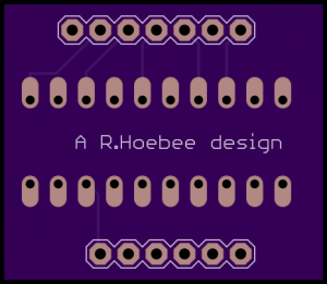
So that is why I created the photocoupler board.
The PCB can be found and ordered here. The board uses 5 PC817 Photocouplers, 5 300 Ohm 0805 resistors and 5 1kOhm 0805 resistors. These values are chosen for a 5V input. If you want it to work with higher input voltages the 300 Ohm resistors need to be replaced with higher resistance resistors. In the video you can see that the photocoupler board can easily handle Arduino PWM signals.
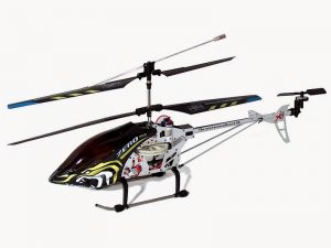
Because there was a hardware problem with the Exceed X8 PRO helicopter of a friend, we decided to remove all the hardware and replace it with custom build hardware. The first thing I did was replace the hardware in the remote controller, here is the blog about that part. In that blog there is also a part about the receiving end, but the hardware used there has been taken out of commission for my newly designed hardware.
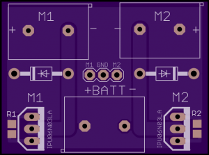
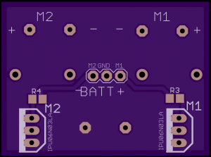
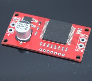
MOSFET board
On the MOSFET board there are two identical MOSFET circuits. Each circuit controls one output which is an amplified version of the input for that circuit. By putting the two circuits on one board space could be saved and the heat dissipation capabilities are enlarged. It also means less wire clutter in the helicopter. The board is designed to be used with IPU06N03LA MOSFETS, but any TO251 package N-channel MOSFET can be used as long as it meets the requirements needed for your motor and controller. Because I’m using brushed DC motors a flyback diode is incorporated in the design. Each MOSFET has its own pull-down resistor to make sure the MOSFET is in the off position when it’s supposed to and to protect the Arduino there is a current limiting resistor placed between itself and the MOSFET. I use 47 Ohm 0805 resistors for R1 and R2 and 10kOhm 0805 resistors for R3 and R4.
Arduino control board
The control board was designed for this project but is released as “wireless board V2.0” on OSH Park shared projects. Because it was difficult to get 3.3v Arduinos with the right pin-out the board is now designed to accept 2 different Arduino pin-outs. Namely the “deek-robot” pin-out found in figure 6 and the cheap “ebay” pin-out found in picture 7. Accept being able to handle two different pin-outs the board is upgraded to accept 3.3v Arduinos and 5v Arduinos. That’s also why there is a 5v regulator and a 3.3v regulator onboard so that the Arduino can be controlled by a unregulated or higher voltage power supply. The nRF24L01+ module is powered by the separate 3.3v regulator so long range nRF24L01+ modules can be used, without asking too much power from the Arduino and so that a 5v Arduino can be used. After having having not enough PWM outputs on my previous wireless boards I’ve decided to change the routing, the new pins are the one used in the Mirf library and can be found in table 1. On the bottom side you can see that there are 3 resistors so the voltage applied to the BATT header can measured thru a simple voltage divider network. Having to voltage regulators makes it also easy to have a 5v and a 3.3v line broken out.
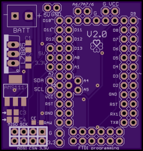
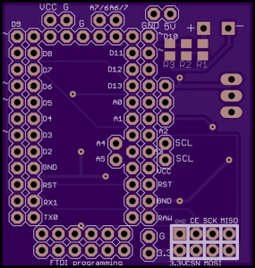
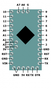
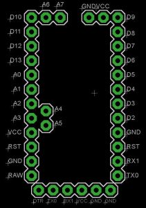
Table 1: nRf24L01+ routing.
| Signal: | RF module pin: | Arduino pin: |
| GND | 1 | GND |
| VCC | 2 | VCC |
| CE | 3 | 8 |
| CSN | 4 | 7 |
| SCK | 5 | 13 |
| MOSI | 6 | 11 |
| MISO | 7 | 12 |
| IRQ | 8 | – |
H-bridge
The H-bridge is the only circuit board that was not custom built but bought. The board is called “Mini VNH2SP30 Monster Moto Shield Stepper Motor Driver ” and uses the VNH2SP30 H-bridge motor driver chip. This board is a bit overkill, but was chosen because of it’s light weight, it needs just one PWM input and it has advanced protection features.
As mentioned above the helicopter used for this product is an Exceed X8 PRO. This is a coaxial helicopter, which means that going forward and backwards is controlled by the tail rotor and rotation is controlled by the ratio of the rotor speed.
As of now the helicopter is still being calibrated for stable flight. Because the main rotors are not identical the amount of throttle for each rotor still needs to be adjusted. The other thing that needs to be adjusted is the center of gravity that needs to be beneath the main rotors.